Virtual reality and online models with Modelo

A few months ago, I ran across this post from Alex Hogrefe's popular visualization blog and was curious about the digital model he had embedded in the page. I hadn't seen an embedded model at that time, though now they seem to be increasing in popularity. My interest was piqued; this summer, I started giving Modelo a try. Check it out below (you might recognize the model, it's one of the sample projects straight from Revit). 

rac_advanced_sample_project By Scott Deisher Modelo »

Uploading
The process of getting a model online is simple (just drag and drop your file into the uploader, and you're done). You can upload Rhino, Revit, Sketchup, Vectorworks, and a handful of other file types. If you upload from Revit or Sketchup, 3d views (Revit) or scenes (Sketchup) are saved as "Comments," which are used to cycle through the views in the online model.

Viewing
You can set a variety of different visualization types. Materials, when turned on in views, tend to show up a little flat (at least in the demos I've seen), but they include a view style called "Architect Effect" which is a take on the ever-popular diagram style of linework and ambient occlusion renderings overlaid on top of each other. That's the view style for the model above. They've done a good job with it; I can easily picture a situation where it might be nice to export a view in that style and do some diagrams with it, without having to use VRay or Make2D. You can also turn layers on and off inside the model.

Mobility and Organization
Modelo would probably be most useful in a situation that demands on-the-go collaboration or viewing between designers and clients. There's no need to download a program or make an account to view a model, which makes it very smooth to send out to a client/collaborator via email or text. Various options for commenting, sketching on top of views, and the like lend themselves to collaboration, and the sketching tools I've seen on their promo page seem like they would be well suited for use on a tablet. The online portal will also host images to accompany the model called "Assets," which means you can run a presentation using an online model but also show 2D drawings, PDFs, etcetera all in the same platform.

Virtual Reality
There's been a general buzz around virtual reality in architecture. But, like many others, I don't have the time or money to do any real investigating into the expensive stuff like Oculus Rift, etc. However, Modelo advertises that it can support easy virtual reality with Google Cardboard. I decided to fork over the $15 for a Google Cardboard and give it a try with Modelo, and I think it's worth trying for yourself. If you have scenes in an uploaded model, you can view the model on your phone, hit the cardboard button, turn your phone sideways and slide into the cardboard, and you're set. You can use this same feature on panoramic images generated in another program, viewed as a Modelo asset. I think Modelo is a great way to test out how you might integrate VR into a workflow or client communication.
Match Rhino and Sketchup Cameras

In last week's post about Flux, I mentioned my own affinity towards the geolocation and shadow features in Sketchup. Even with a relatively large model, Sketchup can produce shadows immediately, and will let users drag the time and date sliders to study how the sun will change the geometry of cast shadows throughout the day and year. With a rendering program like V-Ray, shadows can be realistic and soft, but the geolocation is not nearly as intuitive, and quick shadows are in general much more cumbersome than the few steps involved with Sketchup.

What Sketchup does not do is produce clean, vector-based linework to manipulate later on in Illustrator. It's hard to argue with Rhino's Make2D on that front; it's just way more flexible to have vector lines when making a drawing. Together, Rhino's Make2D linework and Sketchup's accurate and fast shadows are enough data to make flexible, fast study drawings that reflect true solar conditions on a site. The issue is that when importing/exporting to and from Rhino to Sketchup, any "named views" (Rhino) or "scenes" (Sketchup) do not get carried over from one file to the next. This makes perfectly aligning perspective views between programs next to impossible, which means getting a drawing with both Rhino lines and Sketchup shadows is more trouble than it's worth.

*Rhino and Sketchup do both have some photomatching tools to align photographs with models, but neither of them are at all accurate or intuitive enough to match views between the two programs.

This workflow gets past that issue once and for all. I've broken it down into steps to make it more manageable. You'll want to use Flux to do this; while it's not absolutely crucial, it makes the process far easier. You will also need to have the Human plugin for Grasshopper, which I linked in an earlier post. The Rhino document must be in inches (open new doc from Large Objects - Inches) and the Sketchup one in feet & inches.

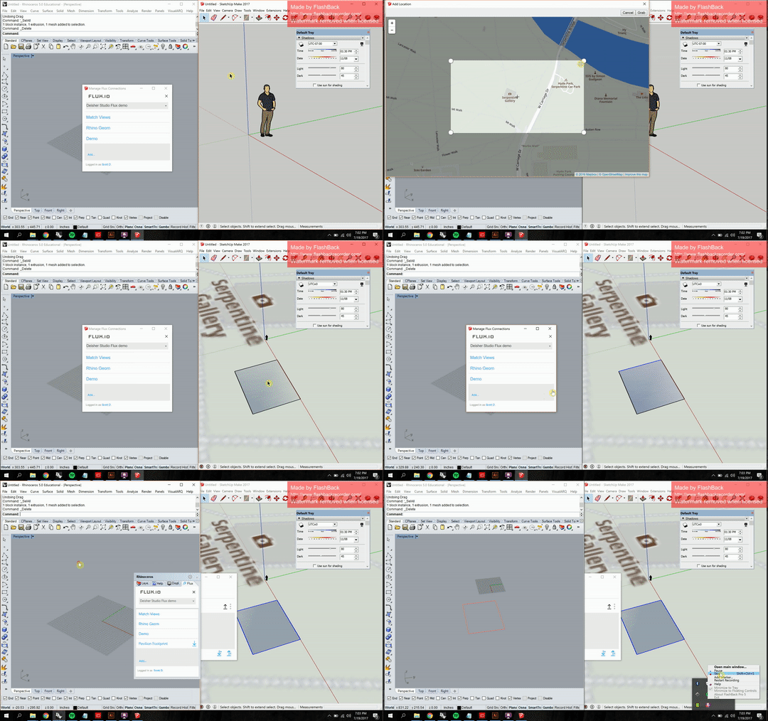
1. Start in Sketchup to set up location data. First, set up geolocation in Sketchup (File->Geo-location->Add location), search for and set your desired location. Draw some sort of marker (I drew a general footprint) to denote where on the site you want your geometry, and send that to Rhino using Flux. This determines where in relation to the origin you will want to draw your Rhino geometry.

2. Draw your geometry in Rhino, and send it back to Sketchup through Flux. Your Rhino model is now shooting geometry straight to a Sketchup model that will reflect how shadows will actually be cast on the site you've determined.

3. Open the Grasshopper script attached at the bottom of this page. Make sure the timer (with the big red arrow) in the lower left is enabled and set to a short interval (right click to change interval). You will see the numbers in the panel on the right hand side change as you move the camera around in the Rhino viewport. If the title under the "viewport" panel doesn't match the viewport you're trying to use, change the number slider at the top left until the word in the panel reflects your desired viewport.

This script pulls the camera data and goes through a series of formatting maneuvers to produce a single script, written in Ruby (the language Sketchup uses). You can then just right click the yellow panel with the camera data and click "Copy Data Only" towards the bottom. Go into Sketchup, click Window->Ruby Console to open the Ruby editor, and paste your data in the command line at the bottom. Hit enter, and voilà!

You can even mess around with Rhino's "DollyZoom" to get skewed perspectives, and the script will match the length of the camera lens between programs. 

4. Run a Make2D in Rhino, and export a 2D graphic from Sketchup. Align the layers in Illustrator. Drag one point of the image to a cooresponding point in the linework, then activate the Scale tool with "S". Click on that same point you aligned to make a reference point (the tiny blue crosshairs in the animation). Then, click another reference point on the image, and hold and drag diagonally to scale in proportion until you reach the second corresponding reference point. Play around with this method of using the Scale tool, it's extremely helpful in other situations too.

Fix up some lineweights, and you're done. Now you can take advantage of the flexibility of Rhino's vector linework along with the accuracy of Sketchup shadows as they would land in the real world. At 6:49am on Septemeber 24th, the above shows how the sun would hit that beautiful object next to the Serpentine Gallery in Hyde Park, London.

DeisherStudio Match Sketchup View.gh

Rhino/Sketchup/Revit seamless workflows

This week I'm giving a quick introduction to Flux, an app for interoperability between various design software like Rhino, Revit, Sketchup, Dynamo, Grasshopper, and other programs like Google Sheets and Excel. Much like Doodlebug, Flux can drastically cut down on time and effort wasted on getting digital models and drawings from one program to the next. It also allows users to collaborate on projects through the cloud using any of its supported apps. I've been using it this summer on a small project during my internship at HKS, and Flux has allowed the project team to divide up modeling tasks between users using both Rhino and Sketchup (some users prefer one software over the other) but still have changes reflected in both programs, since all data is hosted online through the Flux cloud.

Below is a quick demo showing how a project can send data from Rhino to Sketchup. This workflow is valuable because it lets users take advantage of the differences in each program; I prefer the ease and speed of the geolocation and shadows in Sketchup, though I'd rather model everything in Rhino. I've created a new "Project," and each project contains data called "Connections" that users set up to upload different parts of the model to the cloud. 

In the animation above, I'm drawing new geometry in Rhino and creating a new connection through Flux, then sending that geometry using the "Upload" (up arrow) once the modifications are made. In Sketchup, I navigate to that same connection, switch the arrow to "Download" (down arrow), and the geometry downloads and places itself in the Sketchup model. All scaling happens through the app, meaning that I can draw in inches in Rhino and feet in Sketchup, and not worry about scaling the geometry.

Modifying the geometry and updating the connection will automatically delete the previous iteration of the geometry when you download from Flux. The extra lines in the Sketchup view are edges from the Rhino loft, which can be removed (actually just …

Modifying the geometry and updating the connection will automatically delete the previous iteration of the geometry when you download from Flux. The extra lines in the Sketchup view are edges from the Rhino loft, which can be removed (actually just hidden) by using "Soften Edges" which I did in the previous animation.

Every modeling and drawing program has its advantages and disadvantages. The last post about Doodlebug demonstrated another way that we can use the best features in each program without dealing with extra files and conversions. With Flux, you can model freeform in Rhino, take advantage of Revit families, and use the easy geolocation features in Sketchup for proper shadow studies, all without having to export and re-save files every time you want to move your work to another program.

Get a free account and the apps for each software at https://flux.io/
Free accounts get two projects with 10GB storage total (should be plenty for smaller projects). 

The Ultimate Workflow: Rhino to Illustrator Live!

Of the posts I've written so far, this one has the most potential to impact a typical workflow for students, or anyone that produces line drawings using Rhino and Illustrator. This plugin has drastically changed my own workflow.

Doodlebug was created by Andrew Heumann, the same person that makes a few other extremely helpful plugins for Grasshopper (I gave an example of Human in action when I posted the "Carve" component a few weeks ago). 

Doodlebug is a plugin for Grasshopper (available on www.grasshopper3d.com here, but be sure to instead download from here if you have Illustrator CC 2017) that acts as a live link between Rhino and Illustrator. Rather than exporting linework from Rhino into and Illustrator file and touching up the linework from there, the plugin will shoot geometry over into Illustrator in real time while you work in Rhino. The Grasshopper components allow the user to change line weight, line color, and fill—all without ever exporting an .ai file from Rhino, or touching the options in Illustrator. You can set the file up to use layers in both Rhino and Illustrator, and there's even a scaling component so you can draw full scale in Rhino and have your Illustrator file reflect a scaled version.

DeisherStudio doodlebug demo.gif

The workflow above works with Rhino 5 and Illustrator CC 2015 or later. But to add further functionality to the workflow, you can use the Make2D component available in Rhino 6 (I talked about this in my last post) and automate the production of 2D linework from 3D views. See below.

There's more capability in this workflow that I'm not showing in the animations above—clipping planes, using multiple views, getting Rhino layer colors and information loaded straight into the Doodlebug component. I may post again about this workflow later to dive into further details.

To do this yourself, start by downloading the example files at the bottom of the page. For each example, you'll have to first open all 3 files (Rhino, GH, and Illustrator) and then double click the "Toggle" switch and change it to read "True." I've attached screen grabs of the scripts below for reference. Feel free to leave comments for questions and feedback, and enjoy!

Full script for the first example

Full script for the first example

Full script for the second example

Full script for the second example

Automate Make2D using Grasshopper

The work happening in the script I'm showing today is only possible if you use the new Make2D component that comes with the work in progress version of Rhino 6. The developers at McNeel allow Rhino 5 users with a paid license to access the work-in-progress build of Rhino 6 (Windows only). If you have a license key you can access the WIP build here: https://www.rhino3d.com/download/rhino/wip

The new Make2D component means you can work in Rhino and see a real-time update of the Make2D function without having to re-run "Make2D" in Rhino each time you want to export linework. This script will be critical in an upcoming tutorial that explains how to take the linework from the Make2D component and bring it into Illustrator without having to save and export Illustrator files.

The script relies on Grasshopper's Geometry Pipeline which automatically selects all geometry with either a given name or a given layer. This component is extremely useful since it allows the user to just have the script running in the background in Grasshopper and work solely in Rhino, but still have Grasshopper doing all the work in the script.

For the script to work, you have to have saved a Named View that will determine the camera positioning for the Make2D, and type that name into the first yellow panel (mine is called "View1"). Have a look at the script I've attached and some of various components involved. 

Click to enlarge and see what the different components are doing.

Component: "Carve" for boolean subtraction

A common way of working in Rhino, at least in early design stages, is to perform a bunch of boolean subtractions on a simple mass. I've created a Grasshopper component called "Carve" which makes performing subtractive boolean operations in Rhino much quicker and easier to iterate.

The component asks for original geometry, geometry to use for the subtraction, and the layer name for baking the new geometry (this must match an existing layer in the Rhino file). The component automates the subtraction, and resets itself anytime the user moves the subtraction geometry in Rhino. It moves the result off to the side so a user can operate by moving the solids on one side, and immediately see the result of the subtraction without having to turn off any layers or hide geometry.

This component relies on the baking functions built into the Human plugin. Download that at this link: http://www.food4rhino.com/app/human and follow the installation instructions on the food4rhino page.  

To install the .ghuser file, in Grasshopper, select File->Special Folders->User Object Folder, and drag the file into that folder. Then, restart Rhino and Grasshopper.

Note: The carved geometry must be on its own layer. Make sure the subtraction geometry is not set on this layer, or the script won't work.

User component: Carve.ghuser 
Example Grasshopper script: DeisherStudio_CARVE.gh 
Example Rhino file: DeisherStudio_Carve.3dm 

Digital Workflows I: Automate InDesign Book

Programs required: Adobe InDesign, Google Drive desktop app

How it started:
This past semester at Michigan (Taubman College of Architecture + Urban Planning), professor Mitch McEwen taught a studio called "99 Houses" sited in Detroit. As the studio progressed, I led the charge for producing a publication that would pull together all 12 of our projects so we could disseminate the work to the Detroit residents with whom we had been in contact.

The task:
The book needed to be a working document that would be produced concurrently with the work of the studio. This meant I needed to figure out a workflow that would facilitate quickly responding to Mitch's feedback, and easily incorporating revisions from all 12 of us that were regularly working on our projects. This workflow uses separate InDesign files from multiple users, automatically updates them using the Google Drive desktop app, and utilizes the InDesign Book file type to create a live-updating book file with little to no work required by the organizer once the files are set up.

Main idea:

  1. Sync your computer to a master Google Drive folder using the Drive desktop app

  2. Have contributors use a master InDesign file (.indd) template to create layouts

  3. Use the .indd files in your synced Drive folder to populate an InDesign Book (.indb)

  4. Add your front/back matter

  5. Contributors upload their layouts to the Drive throughout the design process

  6. Export PDF to book as contributors update their .indd files

1. Get Google Drive for desktop
Google Drive has a desktop app for both Windows and Mac that will automatically sync the folders you select from Drive to an offline folder on your computer. This is the basis of automating this task; not having to download a bunch of folders each time revisions are made makes everything much easier. At the time I'm posting this, you can find both Windows and Mac versions of the program at this link:
https://support.google.com/drive/answer/2374987?visit_id=1-636295405338551655-3195253946&rd=1
In the settings, you can tell the program to only sync certain folders in your Drive. That way, the program isn't constantly updating all of your Drive files every time you reboot your computer or add files.

Screen Shot 2017-05-04 at 8.53.05 PM.png

2. Set up a master InDesign file with page numbers, contributor names on the master page
Create a new InDesign document with your desired dimensions. Start on page 2 (see image), otherwise your document will start with a page on the right side. Make sure the document has an even number of pages. 

Set up master pages with page numbers. Open the A-Master, make a new text box, and place a "Current Page Number" special character from the Type menu (see below). On these pages, add information that identifies the specific project (I had contributors change their individual names and project titles on their master pages). Put the file up on the Drive, and have contributors use it when they make their spreads. There are a few important rules for contributors to follow so they don't break the workflow:

1. Each person should set up their own folder within the master Drive folder. This folder should include both the .indd file and the linked documents. There is no need to have contributors package their .indd files, they just need to upload the .indd and the links.
2. Contributors must always resave over the same file with the same file name, otherwise the book file will not recognize the change.

3. Set up the InDesign book file
Go to File>New>Book, choose your file location, and a small, empty dialogue box will appear—this is the only visual instantiation of a book file in InDesign. Add .indd files from your synced Drive folder by selecting the three bars at the top right of the box, then Add Document. Add all of your files, and change the order as needed. As you order the projects, the page numbers will automatically update. You can turn this off by selecting "Book Page Numbering Options" and deselecting "Automatically Update Page & Section Numbers." Make sure to turn it back on when you're done, so the page numbers update before you export the book.

Start a new InDesign Book file.

Start a new InDesign Book file.

Add new documents.

Add new documents.

4. Add front/back matter
This step is self explanatory—add the rest of the files you might want included in the book: Cover, Table of Contents, Postscript, etc. I change the numbering options of these files to roman numerals just to set apart the content of the book with everything else. 

5. Contributors make all the changes, you don't have to do anything!
If you aren't seeing the changes, there are a few different things that could have gone wrong:
1. Your Drive settings may not be set to automatically sync the documents in the folder you set up.
2. Contributors may have changed file names.

6. Export book to PDF
Select the three bars, hit Export Book to PDF, and you're done!

Introduction

This blog will primarily discuss digital workflows for architecture students and professionals—particularly using Grasshopper, though some posts focus on publishing and editing workflows using InDesign. Many of the workflows and scripts exhibited here were developed in V. Mitch McEwen's "99 Houses" studio at Taubman College in the winter semester of 2017. Some posts have already been written and are scheduled to go online bi-weekly on Wednesday mornings at 10:00am. 

The Grasshopper tutorials show how to use the program not for generating complex form, but rather for facilitating the carrying out of basic, common design tasks. These tutorials will show how a few basic scripts and snippets can drastically boost design productivity. Other posts will highlight cross-platform compatibility capabilities using Grasshopper, Rhino, Illustrator, InDesign, Google Drive, and various Grasshopper plugins.

Stay tuned for the first post on May 10th, which will show how to facilitate the automation of long-document creation from multiple users using InDesign and Google Drive.